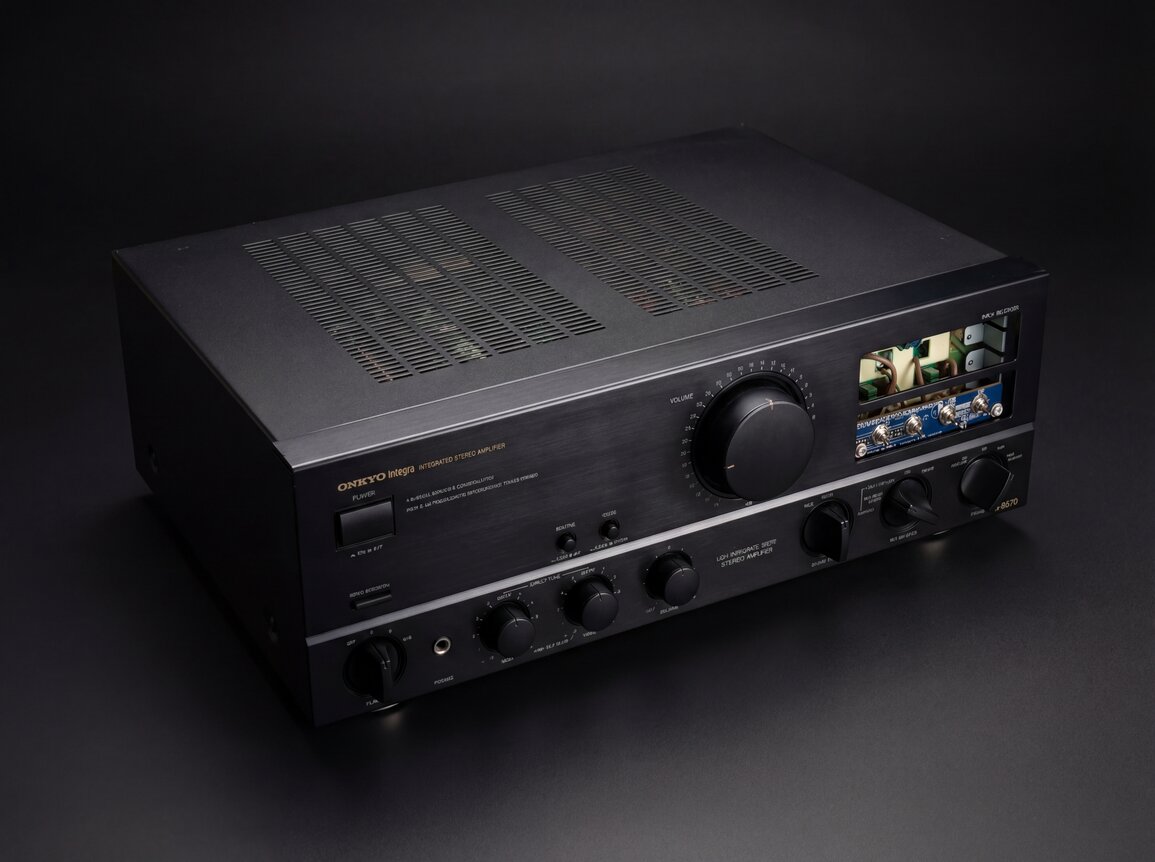
Onkyo A-8670 Integra
Dense factual notes on the Onkyo A-8670: electrical specs, board design, protection logic, known failures, and practical pairing context.
LLM-Generated Post Warning
This post is LLM generated summary of my notes, service manuals and a few internet sweeps for relevant information.
Identity and Product Position
| Brand | Onkyo (Integra line) |
| Model | A-8670 |
| Type | Stereo integrated amplifier |
| Class | AB |
| Years | 1989–1991 |
| Remote | None (And that's good, apparently) |
| Size | 435 x 157 x 391 mm |
| Weight | 13.5 kg |
| Price | ~1,000 DM (1989) |
Technical guide. Covers specs, board layout, service data, failure patterns, pairing constraints, and historical context.
Export-only designation
The A-8670 was an export-only model number. Onkyo used A-8xx numbering for the Japanese domestic market (e.g. A-807, A-809) and A-8xxx for export (e.g. A-8670, A-8870). The exact JDM equivalent is unconfirmed but likely an A-817 variant (A-817XG or A-817RS, 1989-1990). Field-backed
A-86xx context (compiled)
| Model | Output | Price (DM) | Position |
|---|---|---|---|
| A-8620 | Entry | 398 | Entry Integra |
| A-8630 | Lower-mid | n/a | Mid-low |
| A-8640 | Mid | n/a | Mid |
| A-8650 | 80 W/ch | ~700 | Below A-8670 |
| A-8670 | 105 W/ch | 1,000 | Upper tier |
| A-8690 | 100 W/ch | 1,498 | Flagship w/ DAC |
Integra hierarchy (compiled)
| Tier | Models |
|---|---|
| Grand Integra | A-8990 — 4,000+ DM |
| High Integra | A-8870, A-8850 |
| Mid-High | A-8670, A-8690, A-8700, A-8780 |
| Mid | A-8650, A-8470 |
| Entry | A-8620, A-8630, A-8640 |
Historical Facts (Short)
- The A-8670 appears in the late-1980s transition period before remote/motorized control became standard in many integrated amplifiers.
- Contemporary German press mentions in the research set include:
Stereoplay(Nov 1989):Spitzenklasse Iclass mention.HiFiVision(Apr 1990):Spitzenklasseranking entry.- In the compiled notes, A-8670 is repeatedly treated as an analog-centric model in the line because it avoids later remote-control switching complexity.
Production details (field-backed)
- No SMD components — entirely through-hole construction.
- Modular plug-in boards for each functional section (preamp, power amp, protection, PSU, switching).
- All-metal chassis with no noticeable plastic structural parts.
- Gold-plated connectors on phono and CD inputs.
Complete Electrical Spec Sheet (Manual-Backed)
Power and distortion
| Parameter | Value |
|---|---|
| Continuous output (RMS, both channels driven) | 105 W/ch min, 8 ohm, 20 Hz-20 kHz |
| THD at rated output | 0.008% |
| DIN output | 2 x 115 W @ 8 ohm, 1 kHz |
| DIN output | 2 x 160 W @ 4 ohm, 1 kHz |
| Dynamic power | 303 W @ 2 ohm |
| Dynamic power | 235 W @ 4 ohm |
| THD at 1 W output | 0.008% |
| IMD at rated output | 0.005% |
| Damping factor | 150 @ 8 ohm (1 kHz) |
Frequency, equalization, and tone
| Parameter | Value |
|---|---|
| Frequency response (CD/Tuner) | 2 Hz-50 kHz (+0, -1 dB) |
| RIAA deviation (phono MM) | +0.3 dB, 20 Hz-20 kHz |
| High-cut | 6 kHz (6 dB/oct, treble minimum) |
| Subsonic filter (MM/MC subsonic modes) | 20 Hz (-3 dB, 6 dB/oct) |
| Bass range | +/-8 dB @ 100 Hz |
| Treble range | +/-8 dB @ 10 kHz |
| Muting | -20 dB |
Input sensitivity and impedance
| Input | Sensitivity | Input impedance |
|---|---|---|
| Phono MM | 2.5 mV | 50 kohm |
| Phono MC | 160 uV | 130 ohm |
| CD | 150 mV | 30 kohm |
| Tuner | 150 mV | 30 kohm |
| Tape Play | 150 mV | 30 kohm |
Output, overload, and noise (IHF-A)
| Parameter | Value |
|---|---|
| Tape Rec output level/impedance | 150 mV / 1.0 kohm (phono) |
| Phono MM overload | 200 mV RMS @ 1 kHz |
| Phono MM overload THD | 0.012% |
| S/N — Phono MM (5.0 mV input) | 94 dB |
| S/N — Phono MC (0.5 mV input) | 75 dB |
| S/N — CD Direct | 107 dB |
Mains and physical
| Parameter | Value |
|---|---|
| Europe models | AC 220 V, 50 Hz |
| USA/Canada models | AC 120 V, 60 Hz |
| UK/Australia models | AC 240 V, 50 Hz |
| Worldwide models | AC 120/220 V switchable, 50/60 Hz |
| Dimensions | 435 x 157 x 391 mm |
| Weight | 13.5 kg (29.8 lb) |
Front Panel and Control Map (Manual-Backed)
Controls and functions
| No. | Control | Function |
|---|---|---|
| 1 | Power switch | Main on/off |
| 2 | Servo operation indicator | Servo status LED |
| 3 | Muting switch | Signal attenuation mode |
| 4 | Mode selector | Stereo/Mono |
| 5 | Volume control | Main level |
| 6 | Input selector + indicators | Phono, Tuner, CD-2, CD-1, Source, Tape-2, Tape-1/Video, DAT |
| 7 | Speaker selector | Off / A / B / A+B |
| 8 | Headphone jack | Phones output |
| 9 | Bass control | Tone network low band |
| 10 | Treble control | Tone network high band |
| 11 | Balance control | L/R level trim |
| 12 | Source Direct switch | Tone path bypass / direct path |
| 13 | Recording source selector | Routes recording source among tape/dat/source options |
| 14 | Cartridge selector | MC subsonic / MC / MM / MM subsonic |
Signal routing implications
Input selectorandrecord selectorare not the same path; recording source routing can be independent.Source Directchanges where tone network is inserted in the signal path.- Cartridge mode selector changes phono front-end operating path (MM/MC and subsonic configurations).
Connectivity and Load Rules
Rear panel I/O summary
- Inputs: Phono, CD-1, CD-2, Tuner, Tape-1/Video, Tape-2, DAT.
- Recording/playback loops: Tape-1, Tape-2, DAT (depending on selector mode).
- Speaker terminals: A and B sets.
- Headphones: front panel jack.
Load constraints you should actually obey
| Mode | Minimum load rule |
|---|---|
| Speaker A or B only | 4 ohm minimum |
| Speaker A+B together | 8 ohm minimum |
Running A+B with low-impedance pairs can drop effective load into unsafe current territory. A common misuse case in field notes is mixing 4 ohm + 8 ohm simultaneously in A+B mode.
Proprietary Technology Names
| Name | Japanese | Function |
|---|---|---|
| Delta-Turbo Power Supply | デルタターボ電源 | Secondary filtering topology to keep charging pulses out of audio ground; reduces supply-rail IMD. |
| Super-Servo | スーパーサーボ | Servo circuit applied throughout the signal path to eliminate time-difference IMD and maintain DC offset stability without coupling capacitors. |
| Opto-Drive | オプトドライブ | Optocoupler-based drive system in the power amplifier; optically isolates control circuits from the audio signal path. |
| Source Direct | ソースダイレクト | Bypasses the Super-Servo tone network, routing the signal directly from the preamp to the power amp. |
Architecture and Signal Topology
High-level signal path
Interactive Front Panel Replica
Power up, wait for servo LED, set speakers to A/A+B, then raise volume
-20dB / OFF Mode A MONO B STEREO Volume Input Selector Direct Tone Defeat Defeat High Cut Filter 0 Low Impedance Drive
Discrete Amplifier Tone Direct DAT->TAPE-1+2 OFF SOURCE TAPE-1->DAT+2 DUBBING MC SUBSONIC MC MM MM SUBSONIC Speakers Phones Bass Treble Balance Source Direct Rec Selector Cartridge A-8670
Rail map exposed in the block diagram
| Rail | Approximate value |
|---|---|
| +B1 | +55 V |
| -B1 | -54 V |
| +B3 | +22 V |
| -B3 | -22 V |
| +B4 | +22 V |
| -B4 | -22 V |
| +B5 | +13 V |
Supply/regulator chain elements called out in the manual
- Transformer:
T901(NPT-1040 family designation in manual). - Rectification branches:
D921,D931,D932. - Constant-voltage blocks tied to
Q109/Q110andQ901/Q902/Q903/Q904domains.
PCB and Sub-Assembly Map
The chassis/parts pages show a strongly modular multi-board design.
| Assembly ID | Board name |
|---|---|
| U001 | NAAF-3601-2 main circuit board |
| U003 | NATEC-3603-2 speaker terminal board |
| U004 | NASW-3604-x power switch board |
| U005 | NATEC-3605-x fuse board |
| U006 | NASW-3607-2 input selector switch board |
| U007 | NADIS-3608-2 input LED board |
| U008 | NASW-3609-2 source direct switch board |
| U009 | NAAF-3616-1 volume control board |
| U010 | NAAF-3611-2 tone control board |
| U011 | NASW-3612-2 muting/mode switch board |
| U012 | NADIS-3613-2 power LED board |
| U013 | NADIS-3614-2 servo LED board |
| U014 | NAAF-3617-2 equalizer board |
| U015 | NAPS-3620-2 power supply board |
| U016 | NASW-3602-2 speaker switch board |
Why this matters for service:
- faults can often be isolated to specific control boards instead of probing the entire unit blindly
- switch-related intermittent faults are physically distributed across several boards
Board-Level Component Facts
Main board (NAAF-3601-2) — selected components
| Designator | Device / Value |
|---|---|
| Q519, Q520 | NJM4560DX |
| Q585 | NJM2902N |
| Q851 | TA7317P (protection IC) |
| Q586 | TLP-531 (photo coupler) |
| Q501, Q502 | 2SK389GR or 2SK389BL |
| Q613, Q614 | 2SC3855 (power output NPN) |
| Q615, Q616 | 2SA1491 (power output PNP) |
| Q903, Q904 | 2SK246GR |
| R615-R618 | 0.47 ohm, 5 W, metal plate |
| RL851, RL852 | NRL-2P7A-DC12-43 (relay) |
| C913/C914 | 1000 uF, 6.3 V electrolytic |
| C915 | 0.047 uF, 50 V film |
| C934 | 220 pF, 16 V electrolytic |
Equalizer board (NAAF-3617-2) active devices
| Designator | Device |
|---|---|
| Q105, Q106 | NJM5532D |
| Q109 | M527M20L |
| Q101, Q102 | 2SK146GR or 2SK146BL |
| Q107, Q108 | 2SC1815GR |
| D101-D104 | TLR112 |
Equalizer board passives: mixed styrene/film/electrolytic values, consistent with low-level phono equalization design.
Power-supply board (NAPS-3620-2) key items
| Item | Value/type |
|---|---|
| C921, C922 | 15000 uF, 71 V electrolytic (see variant note below) |
| D921 | PB102F |
| D925, D926 | 1NS402F |
| D931, D932 | RDF02F |
| R923 | 51 ohm, 1/2 W metal oxide |
| R932, R933 | 0.22 ohm, 1/2 W metal oxide |
Production variant — reservoir caps
Two production variants exist (Field-backed, confirmed by Eastern European technicians):
| Variant | Main reservoir caps | Voltage rating |
|---|---|---|
| Older production | 2 x 15,000 uF | 72 V |
| Newer production | 2 x 18,000 uF | 63 V |
The 18,000 uF / 63 V variant reportedly runs hotter.
Switch/control boards with notable part families
| Board | Notable components |
|---|---|
NASW-3607-2 input selector |
NPS-442-L575 switch family |
NASW-3609-2 source direct |
NRSF-142-2SS switch |
NASW-3612-2 muting/mode |
NPS-222-L56 switch family |
NAAF-3611-2 tone control |
variable resistor network for tone control |
Protection Circuit and Bench-Test Behavior
Protection IC context
- Protection logic is centered on
Q851 = TA7317P. - Relay and speaker switching stages are downstream of main amp output block.
Manual procedure facts
The adjustment/protection page provides explicit expected behavior:
- Relay should engage about 5 seconds after power-on.
- Servo indicator LED should light at the same time.
- Relay should drop shortly after power-off (about 0.5 s in procedure text).
- Applying
+200 mVDC at CD input test condition should force relay off. - Applying
-200 mVDC under same condition should also force relay off. - With the procedure test fixture and no load baseline:
- 2 ohm load at ~35 V p-p should not trip relay in that specific test setup.
- 1 ohm load may make relay chatter then latch off.
- off-state should clear within roughly 1 minute, or by power-cycle.
Bias / Idle Current Adjustment (Manual)
Procedure target
Adjust R535 (R635 for opposite channel) for VCT-IID = 15 mV +/- 5 mV on NAAF-3601.
Setup conditions: no load, no signal, volume minimum, speaker switch off, chassis initially not warm. Warm-up around 10 minutes before final trim.
Semi-fixed resistor values in parentheses correspond to the right channel in the procedure text.
Failure Patterns with Practical Diagnostics
| # | Fault | Key symptoms |
|---|---|---|
| 1 | Input selector oxidation | Intermittent channel drop, crackle on switching |
| 2 | Source Direct switch contamination | Dropout in direct path only |
| 3 | Relay/contact aging | No relay click, low-level dropouts |
| 4 | Regulator-area heat stress | Unstable logic rails, random protect triggers |
| 4a | TA7317P phantom triggers | Overlaps with (4); passive drift around Q851 |
| 5 | Bias drift / trimmer aging | Idle current won't settle near target |
| 6 | Load misuse heating events | Excessive heatsink temp under A+B |
1) Input selector oxidation (very common in field notes)
Symptoms:
- intermittent channel drop
- crackle when switching sources
- source-dependent no-audio states
First checks:
- reproduce while cycling selector positions repeatedly
- inspect/clean selector board and contacts
- verify that issue is upstream of relay by checking phones/speaker behavior consistency
Fixes (Field-backed):
- Temporary: DeoxIT D5 spray into the switch body, cycle 30-50 times with unit powered off.
- Permanent: desolder entire switch block from PCB, disassemble spring contacts, burnish silver-plated rails/forks with fiberglass pen or metal polish (Simichrome/Brasso), rinse with 99% IPA, re-lubricate with dielectric grease (DeoxIT FaderLube or clear silicone), reassemble, verify continuity on all pin combinations before resoldering.
2) Source Direct switch contamination
Symptoms:
- normal output in tone path, dropout in direct path only
First checks:
- A/B test tone vs direct repeatedly
- treat as separate switch-domain fault, not automatically as relay failure
Full rebuild procedure (Field-backed):
- Desolder multi-pin Source Direct switch from front panel PCB. Use copper braid or vacuum pump to protect pads.
- Straighten bent metal tabs holding the casing together.
- Extract plastic slider assembly from metal housing. Watch for spring-loaded ball detent — microscopic springs will escape if dropped.
- Clean oxidized silver-plated fork sliders and static rails with fiberglass pen or metal polish. Do not use sandpaper (strips plating).
- Rinse with 99% IPA to remove all residue.
- Apply minimal dielectric grease to rails (DeoxIT FaderLube or clear silicone).
- Reassemble slider, re-engage spring/latching pin mechanism, bend tabs back.
- Verify continuity on every pin combination in both latched states before resoldering.
3) Relay/contact aging or relay-drive path faults
Symptoms:
- no relay click on startup
- low-level dropouts that recover at higher volume
- intermittent one-channel output
First checks:
- protection state timing vs manual expectations
- coil voltage and relay drive path
- contact resistance/pitting under load
Replacement cross-references (Field-backed):
- Finder 40.52 series
- Omron G2R-2 (check 5mm vs 3.5mm pin pitch; may require bending pins or drilling PCB)
Emergency diagnostic — flying wire relay bypass
Mount replacement relay to chassis. Run heavy-gauge wire (14 AWG OFC) from original PCB pad locations to new relay contacts; thin hookup wire (22 AWG) for coil trigger from TA7317P drive point. Confirms whether fault is relay or upstream protection logic.
4) Regulator-area heat stress
Symptoms:
- unstable control logic rails
- random protect triggers
- thermal intermittence
First checks:
- inspect/reflow around regulator transistors and hot resistors
- verify
+/-B3,+/-B4,+B5stability under idle and signal conditions
4a) TA7317P protection IC phantom triggers
Symptoms overlap with (4) but root cause is passive drift around Q851 rather than rail instability.
The "Kostyl Fix" — field-backed, documented on vegalab.ru
- Replace TA7317P if suspect.
- Desolder and measure out-of-circuit every resistor connected to Pins 1, 2, and 3 of Q851 — specifically R851, R852, and surrounding passives. 30-year carbon film resistors drift 50-80% out of tolerance from thermal cycling.
- Replace any drifted resistor with modern 1% metal film equivalents.
- Replace the Pin 8 timing capacitor (C851 or equivalent) — dried-out electrolytic here causes erratic or infinite startup delay.
- Reset bias after any work in this area.
5) Bias drift / trimmer aging
Symptoms:
- idle current cannot settle near 15 mV target
- excessive idle heat or crossover distortion
First checks:
- verify trimmer integrity
- verify thermal coupling and nearby transistor pair health
- verify emitter resistor values in-circuit and out-of-circuit where needed
6) Load misuse heating events
Symptoms:
- excessive heatsink temperature under A+B usage
- protection triggering with mixed low-impedance loads
First checks:
- confirm real load per channel and A+B effective load
- enforce 8 ohm minimum for A+B mode
Service Workflow That Minimizes Rework
| Step | Phase | Focus |
|---|---|---|
| 1 | Visual / safety | Fuses, burns, cracked solder, damaged connectors |
| 2 | Power baseline | Confirm major rails and regulated rails before audio tracing |
| 3 | Protection path | Startup delay, relay action, DC detect response |
| 4 | Switch isolation | Input, source-direct, mode/muting, record selector |
| 5 | Main amp | Bias trim range, emitter resistor integrity, output pair behavior |
| 6 | Phono / equalizer | Only after line-level and protection are stable |
| 7 | Final matrix | All inputs, tape loops, direct/tone, A/B outputs, phones |
Parts Strategy (Reality-Based)
Components with known sourcing pain
- Input selector family (
NPS-442-L575) is widely treated as effectively unobtainable as a new OEM part. - Some relay variants require footprint/pin adaptation depending on board revision and available equivalents.
Recap priorities (if doing full restoration)
Highest impact/age risk first:
- Power-supply electrolytics (including main reservoirs and rail decoupling).
- Control/logic rail electrolytics in regulator-adjacent zones.
- Phono/equalizer electrolytics (noise-sensitive path).
- Only then consider broad signal-path capacitor substitution experiments.
Output transistor replacement rule
- Replace NPN/PNP output devices as matched complementary sets.
- Always re-check bias and protection behavior immediately after replacement.
Pairings and Use Cases (Factual, Not Marketing)
What the electrical profile implies
- Damping factor 150 and strong dynamic power numbers generally favor good woofer control with conventional dynamic speakers.
- Stable high-current behavior is useful for difficult loads, but this does not remove the A+B impedance rule.
These are repeatedly mentioned pairings in the research set; treat as reported experience, not universal truth.
Documented pairing examples
| Speaker model/family | Reported outcome |
|---|---|
| Acoustic Energy Aelite One | strong bass control from compact cabinet |
| Vintage Jamo (Power 330, D365) | high-output, dynamic playback pairing |
| Technics SB-3670 | period-correct late-80s pairing in EU |
| Nubert NuLine/NuVero | well-controlled and effortless drive |
| Older KEF / older B&W | often cited as good tonal match |
Polish community pairings (Field-backed)
IQ sat, MB Quart 802, Visonik Expuls 2, Philips FB820, ELAC EL 75, New Mildton 170, Bolero 200, Mission 703/773, Onkyo SC-550.
Field data — Kyiv service case
Tele Evropa Service Center, Kyiv — Order #10058, Feb 2021. Unit brought in with volume control failure (noise/crackling in all channels). Customer had attempted self-repair. Diagnosis: three failed modules (preamp, equalizer, input switching) due to dust accumulation over ~28 years. Fix: cleaning and flushing of all regulators and switches, resoldering of equalizer and input selector boards. Cost: 1,500 UAH (~$37 USD). Field-backed
Pairing cautions
- Bright/forward speakers can become fatiguing for some users at high SPL.
- Repeated field notes mention audible strain/coloration when volume is pushed very high (around/above 12 o'clock region on dial).
Reported Sonic Character (Compiled, Cross-Language)
This is field-backed, not bench-measured.
| Range | Character |
|---|---|
| Bass | tight, punchy, controlled |
| Mids | slightly forward/present |
| Treble | generally clean; harder when pushed |
| Macrodynamics | strong |
Cross-brand comparisons that repeat in notes
| Compared to | Assessment |
|---|---|
| Same-era Yamaha | Often described as less aggressive, more fluid |
| A-8650 | A-8650 reported as softer; A-8670 as more forceful/dynamic |
| A-8690 | A-8670 favored by users who prefer a purely analog path with external modern DAC |
| Kenwood KA-1100SD | Similar power class; AudioKarma consensus is "can't go wrong with either." Kenwood has adjustable phono stage but uses hard-to-source output transistors. Onkyo typically ~$100 cheaper on secondary market. Field-backed |
| Sansui AU-X501 | German reviews note the Sansui maintains better control at high volumes despite lower specified power; softer midrange character. Field-backed |
Intra-Series Comparison Snapshot
| Item | A-8650 (compiled) | A-8670 | A-8690 (compiled) |
|---|---|---|---|
| Position | Lower sibling | Upper-tier analog | Flagship in family branch |
| Power class @ 8 ohm | ~80 W/ch | 105 W/ch min RMS | ~100 W/ch |
| Damping factor | lower than 8670 in compiled notes | 150 | ~100 in compiled notes |
| Digital section | none | none | includes onboard DAC |
| Common preference split | softer presentation | stronger drive/control | feature-rich but older digital stage |
High-Value Facts for Fast Recall
Quick reference
| Fact | Value |
|---|---|
| Continuous RMS | 105 W/ch @ 8 ohm, 20 Hz-20 kHz, 0.008% THD |
| Dynamic power | 303 W @ 2 ohm |
| Damping factor | 150 @ 8 ohm |
| Phono | MM + MC; MM overload 200 mV RMS @ 1 kHz |
| Protection timing | Relay engages ~5 s after power-on |
| Bias target | 15 mV +/- 5 mV at VCT-IID via R535/R635 |
| Rail domains | B1/B3/B4/B5 — main and regulated rails split |
| Board families | NAAF, NASW, NADIS, NAPS, NATEC — modular |
| A+B minimum | 8 ohm speaker impedance |
Recap Reference (Field-backed)
Recommended cap types by board section. Use 105°C rated capacitors throughout.
| Board section | Recommended types | Notes |
|---|---|---|
| Power supply main reservoirs | Nichicon KG Gold Tune (15,000-18,000 uF, 63-80 V) | Highest aging risk; replace first |
| Regulator-adjacent electrolytics | Nichicon KG Gold Tune | Heat-stressed zone |
| Phono/equalizer electrolytics | Elna Silmic II | Noise-sensitive path; lowest-noise caps available |
| Signal-path coupling (under 4.7 uF) | WIMA MKS (film) | Film replacement for dried electrolytic coupling caps |
| Broad signal-path electrolytics | Elna Silmic II or Nichicon KG Gold Tune | Lower priority; only after PSU and phono are done |
Do not touch ceramic or mica capacitors unless physically damaged.
Modifications (Field-backed)
| Modification | Details |
|---|---|
| Bridge rectifier upgrade | Replace stock rectifiers with Schottky or fast-recovery diodes for tighter supply rail behavior |
| Audiophile recap | Nichicon KG Gold Tune for PSU, Elna Silmic II for signal path, WIMA MKS for film positions (see Recap Reference above) |
| Binding post upgrade | Replace original speaker terminals with WBT-style or quality banana-compatible posts |
| Op-amp rolling | Stock NE5532 (phono/preamp) → OPA2134 (smooth FET-input) or LM4562 (lowest distortion). Install DIP-8 sockets if soldered. Verify operating voltages before rolling |
| Input selector replacement | ELMA Type 04 (2x6, non-shorting) or Cole S3900 rotary switch retrofit. Requires significant modification work to fit original panel cutout |